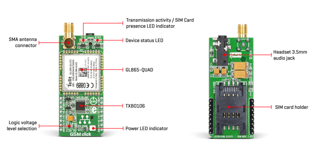
GSM Click, equipped with Telit's compact, four-band GSM/GPRS module, the GL865-QUAD. It covers the 850/900/1800/1900 MHz frequencies. The GL865-QUAD module is compliant with the GSM/GPRS protocol stack 3GPP Version 4 and is also compatible with the eCall EU Directive. This module is the main component of the Click board™ and consists of a range of internal blocks or sections, including the antenna switching section, RF transceiver section, memory, power management, and most importantly, the cellular baseband processor. The module interface consists of a few lines used to report the device and network status, SIM card interface lines, UART interface lines, and device control lines. These lines are routed to the relevant components of the Click board™.
The GL865-QUAD module should be operated with a clean and stable power supply. The required voltage for the proper operation of the module is obtained from the 3.3V microBUS™ rail and is filtered by a filtering network consisting of several capacitors and a ferrite bead.
The digital sections of the GL865-QUAD are powered internally at 2.8V, so the communication data bus lines connecting the main MCU to the module need to be conditioned. The GL865-QUAD provides a 2.8V output from its internal LDO and provides the required reference voltage for one side of the Texas Instruments 6-bit bidirectional voltage-level translator with automatic direction detection, the TXB0106. The reference voltage for the other side of the level shifter is taken from the onboard SMD jumper labeled as G/IO Level. This jumper is used to select the voltage level between 3.3V and 5V from the microBUS™, depending on the type of MCU used and its logic voltage requirements.
The UART interface supports baud rates from 300 bps to 115.2 kbps and supports automatic baud rate detection up to 115.2 kbps. The UART data bus of the GL865-QUAD module is connected to one side of the level shifter, while the other side (shifted) is connected to the relevant microBUS™ UART pins (TX and RX). However, the GL865-QUAD module is designed as a traditional DCE (Data Communication Equipment) device that offers the full UART pin count, including hardware flow control pins (CTS, RTS). These pins are routed to the microBUS™ CS (RTS) and INT pins and can be used in MCU software if hardware flow control is required.
A yellow LED labeled STAT is used to indicate the device's status. The device status is indicated with the STAT LED using the following model:
A red LED labeled TXD, which is used to indicate the presence of a SIM card, is used on one of the module's GPIO pins. As the GL865-QUAD does not provide a specific SIMIN pin, this LED is actually connected to GPIO 1 pin. The configuration of the GPIO pins may be required, but the provided Click library offers functions that properly initialize the module and provide easy communication with the GSM Click. Additionally, the provided application example demonstrates its usage and can be used as a reference for custom development. Both LEDs are driven through NPN BJ transistors to ensure sufficient power supply.
